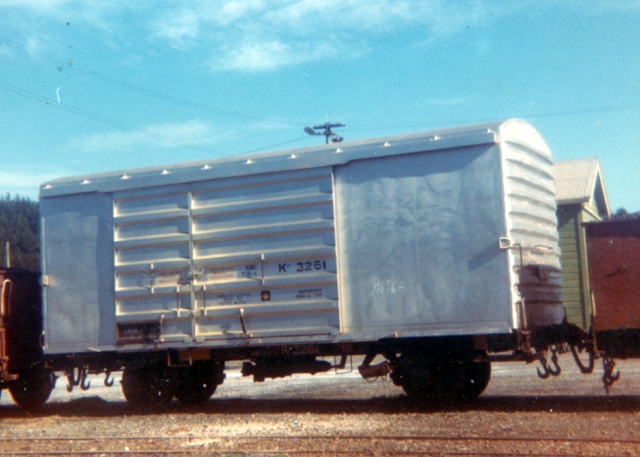
Kp aluminium box wagon
The Kp, along with La steel open wagons, Uc oil tankers, and
Da class locomotives, were to me the image of NZR in the mid
to late 1960s.
Like the La8, I wanted a few Kps and have the capability to
make lots if need be. So for the body decided to see how a complete
master, mould, and one piece cast would turn out, rather than
master a side, end, and roof and cast those for a "kitset"
like the La8.
If you're not into moulding, just ignore the relevant writings
and make as many parts as you need and follow the rest.
Because this model was under construction when these pages
were created I've written a little more detail on the moulding
side of things on a separate page so those interested can take
a diversion there once the body is built and see how that side
of things was done.
Those corrugated ends
The thought of building the corrugated ends of these wagons
put me off for a long time until after much study and staring
and staring at the real thing (my local train museum up the road
has one!) I noticed the shape is actually quite simple and would
be very simple to make. And was pleasantly surprised with the
result.
3D, pure shape-wise, the corrugation consists of rows of triangular-section
strip, with the peaks knocked off, and the ends filed down to
a slope. Simple!
 End corrugation on Kp3231
as seen at Silver Stream Railway.
End corrugation on Kp3231
as seen at Silver Stream Railway.
Building the body
So as normal, use a scale drawing as a guide to cut out the
ends with their curved top and sides from thicker plastic card
for rigidity.
On the sides, there is a single panel line on the right-hand
side - scribe a line for this.
Using the scale drawing as a guide, on the ends glue ten 2mm
triangle rod strips horizontally with even spaces between.
Tip - A great tool for making sure assemblies stay
flat while setting is glass. I steal small sheets from old photo
frames.
Sandwich the assembled ends between two pieces of glass and
set aside for at least 24 hours to set perfectly flat.
Once dry and set, carefully file off the peaks of the triangle
rows until the ridges match the proportional look of the real
thing.
Tip - I've found a better quality nail file a perfect
flat abrasive tool for jobs like this.
Then carefully file the ends of the rows down at an angle
to match the profile of the real thing and hey presto a Kp end!
 Kp end - this ended up
a a test piece as the rows were not evenly spaced.
Kp end - this ended up
a a test piece as the rows were not evenly spaced.
Two are required for the master, or per wagon.
Door panels
The door panels were made similarly using triangle section
strip. After cutting out a panel of 0.25mm (0.010") sheet
the same size as the whole door and adding thin strips on edge
to represent the door ends and their junction, 1.5mm triangle
strips were cut to fit in between.
When all set and dry for at least 24 hours, the peaks were
sanded down to match the look of reference material. Tedious,
but you only have to do this twice if you're just making a master.
Note there are two main versions of the Kp - Kp1 and Kp2.
Mine was going to be the Kp1 as per the NZRLS drawing. Main difference
is the number of horizontal panels in the door - five for Kp1
and six for Kp2. Photo at head of this page shows a Kp2.
 Kp1 doors - this too
ended up a a test piece as the rows were not evenly spaced.
Kp1 doors - this too
ended up a a test piece as the rows were not evenly spaced.
Two are required for the master, or per wagon.
Sorry no photos for this next part of construction but will
try to explain as best as. . . maybe add some sketches later.
. .
Next, an inside roof was carefully (and twice!) measured and
cut from thicker plastic sheet, matching the inside dimensions
of the intended box wagon. Allow for thicknesses of your ends
and sides.
Once the ends have set you can assemble the two sides and
ends to the inside roof to form a rectangular box - the inside
roof sits level with the top of the sides - the ends' curved
sections will be sticking up.
Tip - Use a glass sheet for getting the base to sit
perfectly even, and some form of squaring up tool - I use my
aluminium-section modelling mitre box that seems to do the trick!
So you should end up with a Kp wagon without outside roof
and doors. And other detail bits.
Next using the end curve profile from drawings, minus 0.25mm
in height, cut out about five or six "ribs" that will
sit on the inside roof to ultimately support the outside roof
and glue them vertically in place evenly spaced. It'll end looking
sort of like a part of an aircraft wing construction.
Include a rib at each end, glued to the inside ends, that
will form a "ledge" onto which the roof skin will sit.
And like aircraft wing construction, the next step was to
skin it. Carefully measure (twice!) and cut out a rectangle of
0.25mm sheet that will ultimately fit the roof, curved over the
ribs, and flush with the sides and long enough to sit snugly
on the afore-mentioned ledge on the ends.
Carefully measure (twice!) and lightly scribe the roof panel
lines using drawings as a guide.
Tip - Before glueing on, the cut out roof skin can
be given a curve to avoid stress by wrapping it on a piece of
plastic pipe like 25mm conduit and running under hot water. It
doesn't have to have the full 25mm curve - it's just enough to
give it a bit of a curve to make gluing in place easy.
You could always use a block of balsa for the roof instead,
but I like the "engineering" of the wing-like construction
:-)
Next carefully measure position, then glue on the doors, and
add the door stops from a tiny section of angle strip suitably
shaped. See drawings and photos for reference. Note the Kp1 door
stops are mounted higher than the Kp2. Damn! Rivet counting again.
Again using drawings as a guide, add strip to represent the
top only of the top door runners. And small squares for the little
end-caps.
The side of the top door runners and the bottom door runners
(the latter to be angle strip) will be added to the casts rather
than now otherwise they would be broken off in the de-moulding
process. Remember the mould halves are going to come away sideways
from the longditudinal centre-line and would therefore "hook
up" the top and bottom door runners if present.
The little trianglar top door runner support brackets were
first glued on as tiny square shapes fom strip, then when all
dry and set for at least 24hrs, filed off gently and evenly to
45 degrees or so with a nail file.
It really is a good idea to add as much as you can to the
master to save work later on the casts. You can't add the handrails,
but to make it easier for mounting on the casts, carefully mark
all the positions of where they will be mounted and using a 0.015"
or so drill bit, create shallow dimples. These will be starters
for drilling holes for the handrail wire on the casts.
 So there we have it.
A Kp body (master). Very pleased so far I am.
So there we have it.
A Kp body (master). Very pleased so far I am.
Note also in the full size image you can see the handrail locating
dimples
on the 4th corrugation up, middle, and on the left-hand end edge,
on the 1st and 4th corrugations up.
To make the body stronger and more rigid, wether casting or
not, the inside is lined with some thick plastic sheet, and a
divider put in about half way. This will give strength to the
sides and ends - especially the sides. Don't make the lining
come all the way to the bottom as the chassis floor will fit
there and add its own strength to the box.
This extra lining will add a bit of weight too, although we
don't want too much for fear of a top-heavy model!
To be nice, neat and tidy, my lining should really have come
down to within 1mm or so of the bottom of the sides and ends
- depending on the thickness of intended floor.

At this point the body is ready for moulding and casting so
for those of you interested, take a
slight diversion. . . .
otherwise. . . .
Ready to add detail to the bodies
(cast or otherwise)
First the inside of the bottom was carefully (always carefully
and twice) measured and a thick (1 to 1.5mm) plastic card rectangle
that will become the floor was cut to size. The floor sits inside
the box bottom, flush with the bottom of the sides and ends.
 Floor added to one of
my Kp body casts
Floor added to one of
my Kp body casts
Next things added were the top and bottom door runners.
The bottom runner is simply a length of 1mm right-angle plastic
(or I used brass) strip that runs the whole length of the bottom
edge of the sides.
The top runner side is a strip of plastic fitting between
the inside of the end caps and inside of the runner top. Once
glued in place and set, any joints were cleaned up for a smooth
tidy finish.
An extra, thinner strip with angled ends for a gutter was
added to the bottom edge of the top door runner, above where
the doors are in the closed position - see drawings and photos
for reference.
 Top runner side and gutter
(white plastic strip), and bottom runner (brass) added,
Top runner side and gutter
(white plastic strip), and bottom runner (brass) added,
along with headstocks from plastic C channel strip.
Before adding hand rails and door grabs, etc it's probably
best to add the chassis of your choice at this point.
The Kp uses a 13ft chassis and solebars were added after initial
pre-assembly in my chassis jig.
As a bit of added detail a brake cylinder and attached "pipes"
were glued in place just to make the undergubbins less sparse.
Once all had set the undersides received an overall coat of
black as per the prototype's factory finish.
Then it was on to a little bit of undergubbins.

 Kadee coupler boxes glued
in place, chassis added, wheels fitted,
Kadee coupler boxes glued
in place, chassis added, wheels fitted,
just adding brake cylinders and "pipes" and painting.
The bodies then received a base coat of Humbrol Aluminum -
lovely paint this. A couple of bodies I tried a flat gull grey
instead for that faded aluminum look.
 Coming along nicely
Still to do some varying density washes of a murky grimy drab
dark khaki green for a bit of weathering.
Then shunter's step, handrails, and footbrake to be added.
more to follow. . .
Home |