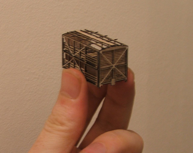
J5 Sheep wagon
 NOTE: Strictly speaking this isn't a scratch-built project but, as the athour of the original project puts it ". . .a scratch builder's aid set of parts. . ." So after a crash course in CorelDraw (well, learn as you go really!) the original BatchBuilt NZ120 scale drawing was re-sized to OO scale or 4mm to the foot, allowing for a change in material thicknesses, and a bit more detail added along with slightly altered construction method. e.g a bit more detailing on the ends, reshaped doors and correct double flooring. Instructions, as well as the original BatchBuilt NZ120 scale CAD drawing and licence, were downloadable from the NZ120.org site.
And if anyone's keen, you can download my OO re-scaled (read "tweaked" for licence purposes) version that is a CorelDraw file, and is laser-cutter-man ready.

Please read the licence conditions. After all, the original author put in a LOT of work to make this "scratch-builder's aid" available for us to make a pretty stunning model.
After hunting around for laser cutters, contact was made with Mini Building Creations for advice and possibilities. Mike had worked on producing NZ120 scale cuts before and was very very helpful in getting my OO version smokin'. He is highly recommended for any modelling laser work. After a test cut, advice, and deciding on materials, a few minor tweaks to design, we (I say we because the laser cutting skills are a big part of this!) ended up with a very pleasing built up prototype.
 On closeup you can see it needed more care in cleaning up the parts before assembly - a lesson I never seem to learn :-( in too much of a hurry to see the finished product! So pleased with the prototype cut, especially detailing on the ends, that it became the final and so six more were ordered and are now awaiting construction. Unfortnately construction steps for the prototype weren't recorded but will do so for this next lot!
So here's how they arrive in the post. . .
 Weird objects extreme right are cuts for Uc4 and later model Tanker cradle sandwiches. Let's get started First job, peel off the backing. Easier to leave the parts attached to the sheet while doing this. . .

After peeling off all the paper backing, remove any sticky-stuff left behind with something like "DeSolv-it". Then it's a process of carefully cutting away each part from the sheet. While doing this I was surprised at the strength of the polyester material. The parts look small and fragile but can easily take my stubby-fingered, ham-fisted handling. I don't know how the NZ120 lads do it with their teeny version! All parts are given a light scuff over with sandpaper to remove any melt edges from the laser cutting process. Failed to do this on the prototype and you can see a really bad case of melt on the edge of the bottom floor just above the axlebox closest to camera in the heading photo. Don't make the parts all smooth and shiny - a scuff-over will add a bit of "woodgrain" to the look.

NOTE: While cleaning up the parts, file 0.5mm off the side and bottom edges of the "End inside" part as identified above. I missed making the adjustment to the CAD file between prototype and final cuts :-( It's only 0.5mm but will give a more accurate fit when assembling the side and bottom grated floor pieces. Next is to wire up the doors and sides to replicate the "fence" rods. Single wires from a multi-strand piece of mains cable (it was what I had to hand) were used on the prototype but would rather use stiffer, 010" piano or brass wire. Take the two sides and identify the insides - there are grooves cut into the vertical posts, on the inside surface only, to house the wire rodding.
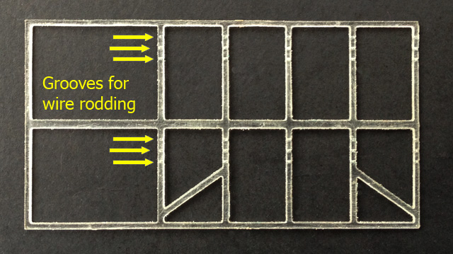
Lay the sides face (outside) down on a worksurface e.g. a sheet of glass from a picture frame, so the grooves are visible. Measure (TWICE) and cut 12 lengths of "rodding" to span the five vertical posts from door frame to end and glue in place. Notice the door post grooves are only "half-width" for a neat finish. Also there are two lengths for each inside end piece, and two for each door. Fiddly but wow, worth it in the end.
 Assembly instructions During assembly, please refer to drawings and any reference photos as well as mine to confirm correct orientation of parts. And do dry fit parts before glueing just to confirm correct fit and correct orientation.
Glue an outside end to one side. Take careful note of their orientation as follows. The rodding on the ends AND sides, are on the INSIDE. The door openings in the side are to the right. The outside end glues to the outside edges of a side. Just emphasising, the rodding will be on the inside of the ends and sides. I used a sheet of glass and a block of Duplo to make sure everything is perfectly square and lined up.
 Note that all rodding is on the inside and door openings are to the right! 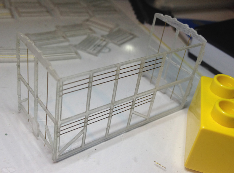 and the ends are glued to the outside edges of the sides. Next, the inside ends are added. Funnily enough, the inside ends are glued on the insides of the ends, sandwiching the end rodding. Make sure the inside and outside end tops are flush, and that the etched detail on the inside end is facing OUTWARDS.   Next, add the triple guard rail planks to the inside of the sides, below the horizontal rods. Use drawings and a door temporarily in place to line up exactly where they go. Use an etched grating floor part to cut the rectangles for the real floors from 0.030-inch white styrene. The top deck 0.030-inch styrene floors can be test-fitted then glued in place at this stage, lining up with the horizontal side runner below the guard rails. Strips of styrene are added on-edge, lining up with the sides' vertical posts, for the raised false floors to eventually sit on. Look at the laser cut and etched false floors (in real life wooden grating) and you'll see gaps in the lengthwise etch marks. Crosswise strips of styrene are added there to further simulate the wooden grating. NOTE the strips are not quite full width so cut them 1.5 to 2mm too short. This is to allow the grating floor to fit snugly under the guard rail planks on the sides when sitting on the risers. See photo below.
 false floors (wooden grating) with added strip detail. In the background you can see the 'double-J' or S wagon under similar construction. Next the handrails and door handles can be added. These are bent from 0.040-inch phosphur-bronze wire. For the handrails, I made a 90-degree bend approx 2mm long, then used a piece of spare ABS strip lying about, trimmed to 8mm wide, and further bent the wire another 90 degrees and snipped off 2mm from the bend. Repeated in my case 20 times - four handrails each for four wagons, plus the S wagon. For the much smaller door handles, again using the same 0.040-inch wire, I made a 90-degree bend approx 2mm long, then using the nose of the pliers, I found putting the wire in a grip-notch, a couple from the tip and bending 90 degrees again, provided just the right size. Repeated 24 times - four handles each for four wagons, plus another eight for the S wagon.
 The plastic sticky looking thing centre-right is a jig used for getting correct and consistent gap or 'standoff' when fitting the handles and handrails.
Next the lasercut crossmembers are added to the sides and ends. I just used a spot of superglue in the middle, and at each corner. NOTE that the side crossmembers can go rightside OR inside out, BUT the end parts only go one way - the larger top corner 'plate' goes to the left, and on the real thing is part of the support for the top sliding door's rail. See this in the photo below.

That's about as much can be done before first painting. The insides of the wagons and the insides of the sides and doors to be added later are roughly done, basically a splash around with thinned Humbrol 70. When normally applied, this paint has a nice weathered, smokestained, red-oxide look about it. I thinned it down to go further and create a rough patchy streaky look associated with general messyness created by the wagons' normal cargo. Once the paint has dried, the floor grates are added to the top decks, and also to the bottom floors that will be added later. The grates have only been painted on the underside, and being clear polyester, you can now plainly see the thin strips of styrene added for extra detail.
On the right, a pile of bottom floor sandwiches for adding later.
Next the remaining sides are added, and paint splashed liberally around the inside to cover any bare patches. The top and bottom deck gratings are then washed with whatever looks like wood, that has been sheep shat on and sluiced and left to bake in the midsummer sun. Repeatedly. And not necessarily in that order. I used first a grey wash over the initial red oxide, followed by a wash of a grimy greeny looking mix I have lying around for weathering in general. Looks ok to me and the affect I was aiming for. When the bottom floor/grate assemblies have dried, they can be stuck into the bottoms, ready to take a chassis.
In the background, the S-2 is following similar assembly and treatment.
Next the chassis and couplers of choice can be added. I added my mark 1 cast solebars - just to use remaining ones up - assembled using my jig. Will probably replace these chassis with MMW foldup brass ones - much nicer! My current supply of couplers was Kadee #5 boxes and #148 whisker couplers. These were assembled and simply glued in place centrally at the ends of the bottoms. Lastly, lengths of styrene 'C' channel were cut and glued on the end edges each side of the coupler boxes to represent the headstocks.
 Wheels are added just for testing - North Yard 10.5mm spoked.
Brake lever bits were added from brass micro strip. Next was the roof. Decided not to use the lasercut part as it didn't quite have a realistic stringers-on-rafters look. So cut strips of brass micro strip made replacement 'rafters'.
  For those of you with a black and white monitor, red shows the parts that were removed.
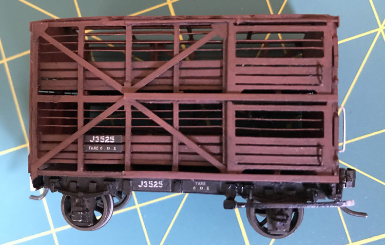
Applied a few more washes of Humbrol 70, then white for the handgrabs and shunters steps and handbrake end. Then 'decals' were laser printed onto thin A4 paper and cut out and stuck on using Humbrol matt clear as the glue, followed by a few coats to seal them all in.
Finally finished after how many years? And as hoped, they look great in a rake in an appropriate setting.
|


