H-4 cattle wagon
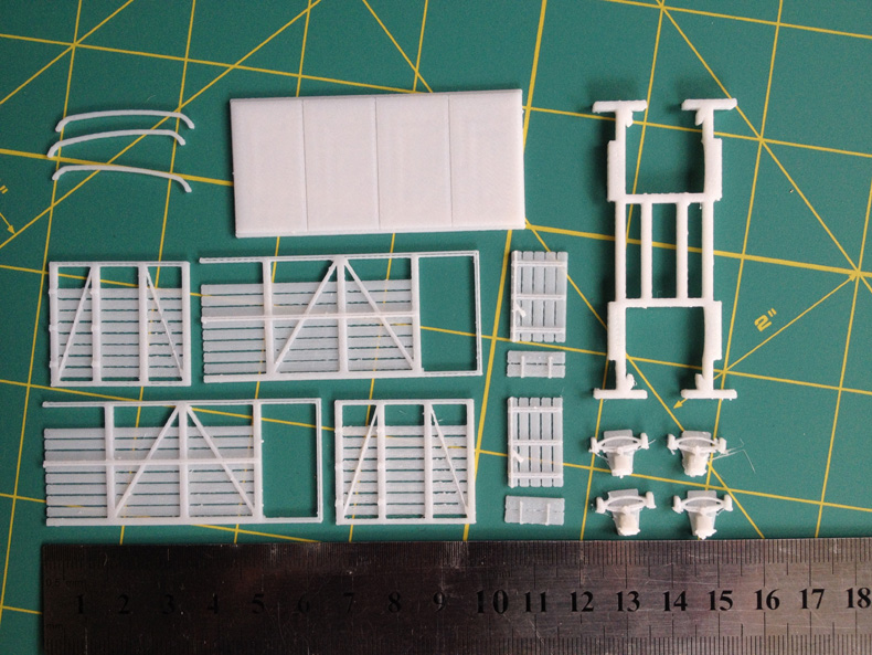
First look. I love building kits. Have done so all my life, starting with a 'Lincoln' brand Lancaster bomber in the mid 1960s. More recently, my scratchbuilding of NZR wagons has been inspired by that kit building over the years. For those wagons I ended up making kit part masters, mainly from styrene, and moulding and casting these into kitsets of parts. So now this is the 21st century, where 3D printing is coming to the fore, and whole models are being produced in mostly one print. Luckily for me at least, some producers like Matt are printing 3D kits of parts, so we can all still enjoy the pleasure of kit building. This H wagon (appears to be H-4 with the 9ft wheelbase) kit comes in a ziplok bag of parts, and includes instructions, and everything you need except for wheels and couplers, and any detail parts like brake levers and hooks and chains. A nice feature is the ability to make a model with the split doors open or closed - the smaller lower one acts as platform to a stockyard's loading ramp. The chassis is nicely done too, and looks like it will make a nice square sturdy platform for body and wheels. The print is overall very crisp, although some minor cleanup work is needed with a hobby knife here and there. The usual surface texture of 3D prints is mildly evident, but I won't sand it off as it will act as a very nice authentic wood finish. Attention to detail includes a nice little indent on the inside of each axle box as a guide for drilling a hole for wheel bearings.
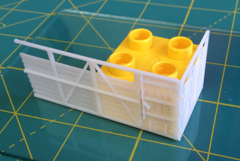
Right, let's get started. . . the body After cleaning up bits with a hobby knife and nail file/emery board, the sides were laid face up on a sheet of glass and the doors dry fitted before gluing in place with just a couple of drops of superglue. Once set, flip over the sides and add a bit more superglue to strengthen. Next it's time to join the sides and ends so you have a pair of 'L' shapes. I've found the best way to get everything square in all three dimensions is to use a Duplo block (kindly donated by the grandchildren) and a sheet of glass from an old picture frame. Just line them up and tack with a spot of superglue - just enough to hold the two parts together.
Once dry you can then apply a bead of superglue along the inside to make the joint more solid and permanent.
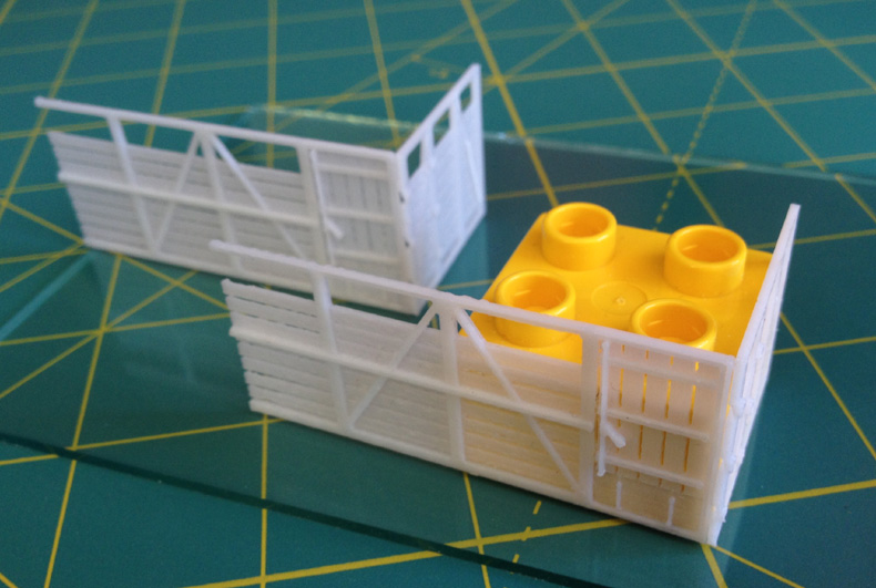
The two L shapes are then lined up and brought together to make a box shape on the glass sheet, and a few spots of superglue applied to tack them together. Once set, the floor is dry fitted in place, with a bit of filing where neccessary. This piece has a nice little ledge all the way around for the body to sit on, making alignment and fitting very easy. The floor is tacked in place with a few spots of superglue and when set, the whole assembly is given the once over and when satisfied all is good, beads of superglue are run along all the inside joints.

Now for the chassis The four axleboxes are cleaned up quickly and very easily with the hobby knife. Then using a hand chuck with a 2mm drill, and the indents provided as a guide, holes are drilled for the 2mm 'top hat' brass bearings. These bearings are available from many online model stores, including Hattons (selling the Romford brand I am using at the moment) or New Zealand's own North Yard. Be careful not to drill all the way through. Just a little at a time and check as you go by test fitting a bearing. The hole only needs to be deep enough for the rim of the 'top hat' to sit on the inside face of the axlebox. The printed material is quite hard compared to the resin or polystyrene I have worked with in the past, and in a way, easier to take it easier with drills and knives!
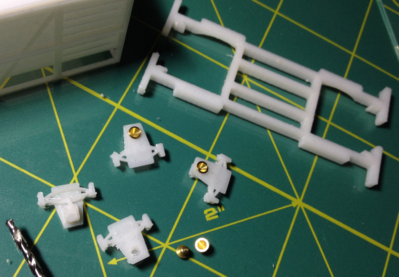
Once satisfied, fix the bearings in place with a drop of superglue - without getting any glue on the bearing inside surfaces.
The chassis part is placed upsidedown on a sheet of glass, and axleboxes are then spot glued in position. The top of the axlebox part should be resting on the glass sheet so when viewed in the normal position, it is flush with the top of the chassis solebar. When satisfied all looks nice and square, run a bead of superglue all around the joins.
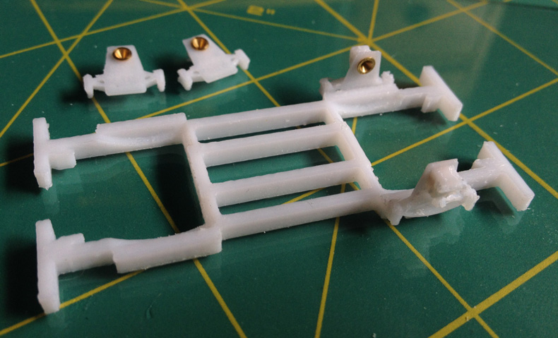
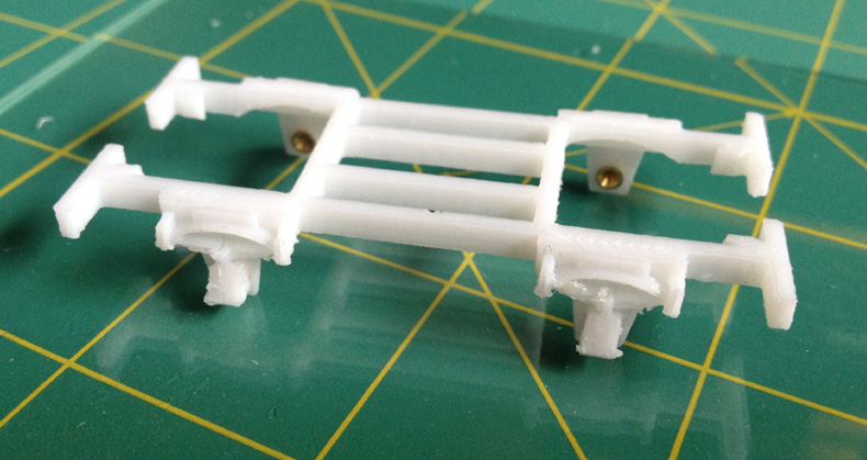
Although there are no locating tabs/pegs/holes on the solebars for the axleboxes, it is very easy to get these lined up squarely - especially when using the glass sheet. The top tab of the axlebox piece is square and so if flush with the top of the solebar, all is good.
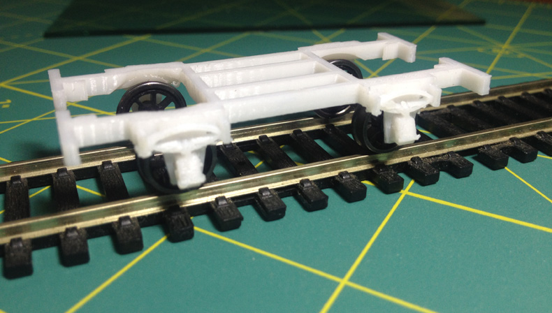
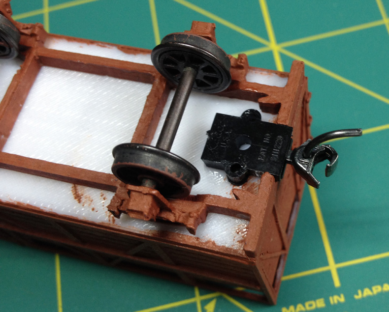
Next is to test fit the wheels. The design appears to be made for 26mm length axles, so I fitted some North Yard 26mm axled 10.5mm spoked wheels. I use these as they are the closest to the usual NZR 30 inch (10mm in 76th scale) goods wagon wheels. These wheels rubbed on the inside of the mounting pad of the axlebox (arrowed), so a little bit of paring with the craft knife allowed enough clearance.
With the wheels test fitted, the whole assembly was put on track and thanks to the bearings, is extreeeemely free running.
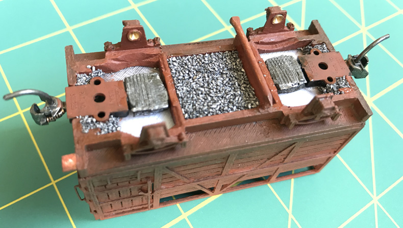
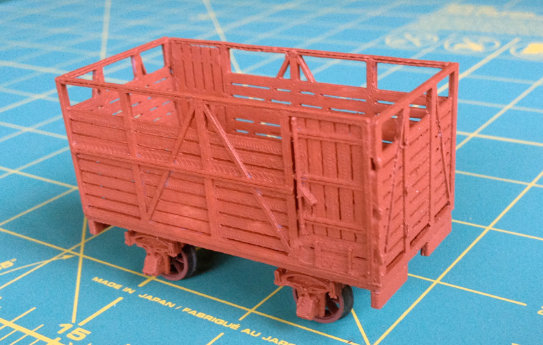
At this point you would normally glue the body to the chassis, add couplers, and add the roof rungs, maybe a brake lever and ratchet, shunter's steps, then splash a bit of paint about, add decals, done. But first, I like to add a bit of weight to plastic/resin models in the form of granulated lead glued anywhere and everywhere in the chassis underside. To this end, using a hacksaw blade, I cut off a couple of the chassis struts (marked red in the photo) to make more room for the lead. I take the view that all my wagons are built to run rather than have their undersides closely inspected. 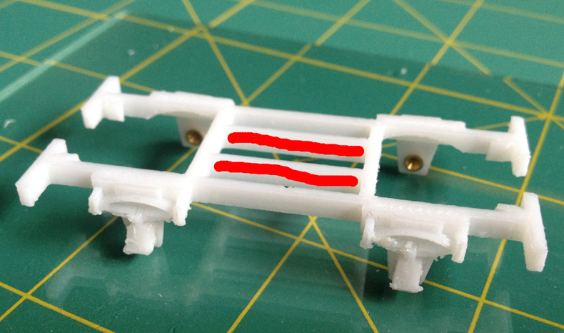 Now for painting It's best to leave the roof rungs off until finished painting the inside. I've just thinly rough coated the body and chassis with Wattyl rust preventer red oxide primer, and the wheel spokes and rims with Humbrol 70 Brick red matt.

Body can now be glued on to the chassis. . . .
And then add couplers of choice. At the moment I am doing Kadee #148 standard whisker types. If you haven't assembled Kadee couplers before I've added a quick how-to on my chassis page.
Check the couplers are the right height against a Kadee coupler height gauge, or against other wagons that are known to be correct height. Looks a smidgen high here but near enough.

Before finishing off the painting and weathering and adding the roof rungs, I'm adding a bit of detail. I usually add the footbrake and ratchet from bits of brass microstrip, handrails from wire, and some shunters' steps from little squares of styrene strip. Extra detail to add to this wagon is the end ladder rungs or strengthening braces whatever they are, along with the door opening struts. Matt has printed the ends of the braces/rungs so they can be used as a guide.
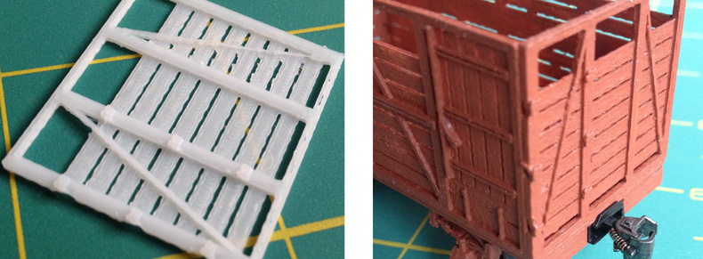
Added end detail rungs from thin strip styrene, and bent up some wire for the handgrips that were then glued in to drilled holes.
Getting to the finishing stage now. Added some weight into the gaps in the underframe, using squished and grated lead from fishing sinkers and lashings of Superglue to stick it all together. This then gets a coat of a dirty grimy colour to seal it all in.
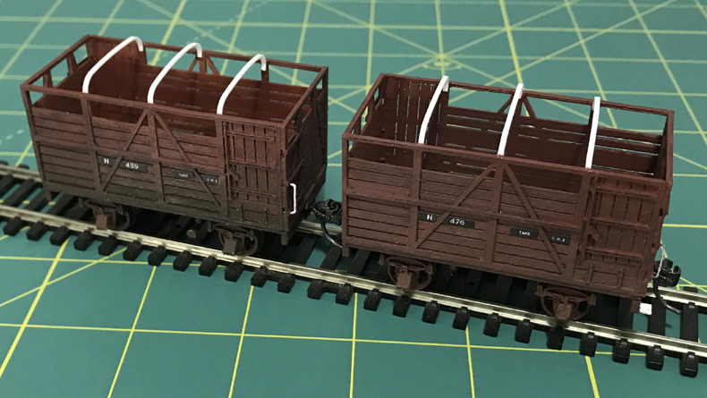
The nail by the way makes an axle and mount point for the hand brake lever! Splashed all about some thinned Humbrol 70, the Wattyl red oxide, and some of the dirty grimy mix I have. The kit supplied roof tie bars seemed a little chunky for me so instead of just filing them down, I bent some new ones from 1mm x 0.5mm plastic strip. Wasn't too fussy about getting them too perfect and even. Just near enough as the real life ones would have not been perfect after decades of use.
The decals are my CorelDraw creations, and are just laser printed onto normal A4 paper and cut out, then stuck on using Humbrol clear matt as the glue and when dry a couple of layers just to seal and finish off. Shunters steps were added from thin plastic, and on the rear wagon above, you can see the head of the nail, filed flat a little bit, where the hand brake lever will be fitted.
And with the roof straps painted, I'm just waiting for some more 1mm brass mini strip I use for bending up the brake lever. I suppose I could have cleaned up the parts a little better, but . . .. .
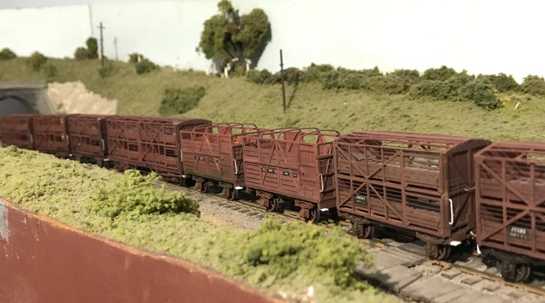
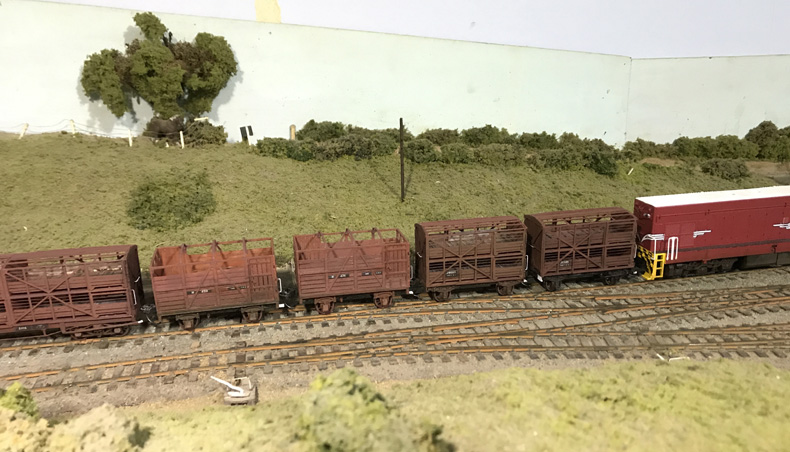
. . . . they sure look good from two feet away - good old two foot rule!
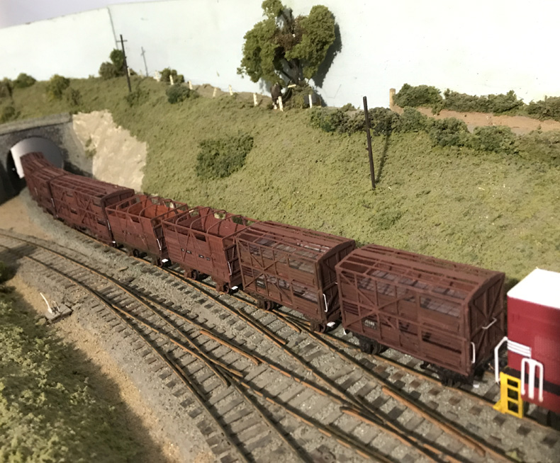
And that's about it for this project. A HUGE thankyou to Matt for printing these kits. They gave me a real buzz to build, and really do complement my stock train. |