Goods transfer shed
Overview of the original
The shed I want to build is based on the mid 1960s-built shed
at Gracefiled yard, Lower Hutt.
As yet unable to establish exact date of build, but an idea
can be got from various Retrolens
or Whites Aviation
aerial photos in which the shed cannot or can be seen. A
search on 'Gracefield' found plenty to look at.
Also Patrick has an excellent resource in his New
Zealand Rail Maps website
 May 1963 and there's
no sign of the shed. Or the office.
May 1963 and there's
no sign of the shed. Or the office.
 Looking quite new in
October 14 1965.
Looking quite new in
October 14 1965.
The new yard office that I also want to build eventually, is
also there now - bottom edge, right.
(Credit - Both of
these pics are snips from Whites Aviation photos stored online
at our National
Library)
I used to hang around Gracefield yard and Woburn station a
bit as a youngster in the school holidays, watching all the shunting.
The yard was also used as a shortcut in the weekends when
nobody was about, to fishing spots off the Seaview reclaimation
and Point Howard wharf. Took the odd
photo of a wagon or two while passing through. Just wish
I'd taken some of the shed!
Like any project, you have to gather info - as many pictures
and drawings of the proposed subject and you can.
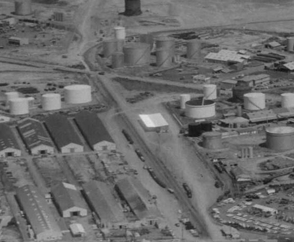
A plan view was easy to get hold of thanks to the Hutt City historic aerial views website,
and using known sizes of track gauge and wagons pictured in the
yard, it was relatively easy to calculate measurements.
 Snip of 1977 view from Hutt City historic aerials
Then on the Valley
Signals site I found some pics of the actual shed during
the last days of the yard in 2002. . .
for example. . .
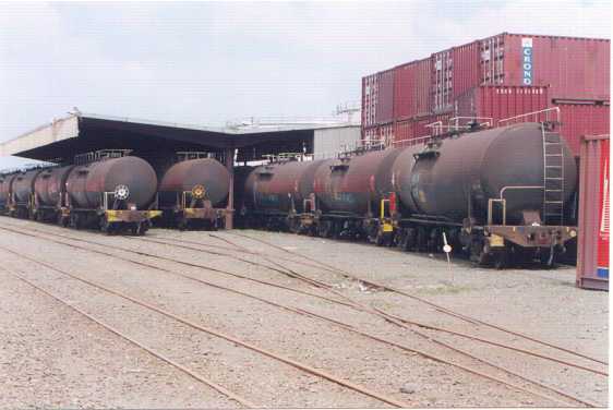 The shed, looking south-west-ish
(Credit - The Valley
Signals website)
Then there's these captured screen shots from a video segment
"K class hulks" I stumbled across on an old Rail
Scene VHS tape number 8, that has the panning camera catching
some fuzzy but useful interior detail - especially underside
detail of the roof. For example. . . .
 (Credit - Rail
Scene VHS tape number 8)
(Credit - Rail
Scene VHS tape number 8)
So using all this info I was able to create reasonably close
1:76 scale drawings of roof plan and end elevation.
The roof will overall measure in OO scale, 680mm long and
258mm wide, so quite a decent size.
The 4ft 6ins platform edge to track centre, and 2ft 5ins platform
height measurements are from NZR specs, while the 13ft between
tracks is calculated from the aerial views.
And below is a scan of my scribbles for the end elevation,
south end.
790.jpg) Click on the image for
enlargement.
Click on the image for
enlargement.
Construction overview
The structure consists of nine supports or ribs, each made
up of H beam main and platform posts, and rafters made up of
an I beam joining the two posts at roof level, then tapering
I beams extending outwards each side.
There are end walls to provide shelter from prevailing northerly
and southerly weather.
A channel gutter runs atop of all the main posts where the
two roof panels meet, from which there are some gullies with
downpipes coming down next to some of the main posts for drainage.
Several roof purlins join all the rafters, to which are fixed
corrugated roof panels - including some clear panels for skylights.
The corrugated material that is also used for the end wall
sections and roof awnings, appears to be a jumbo size, and in
measuring and calculating, it's close to a five or six inch pitch
(distance peak to peak of the corrugations) rather than the usual
household three inch.
There is a narrow concrete platform running the length of
the shed, and similar height concrete foundation walls extend
out at each end on the road side to support the end walls. There's
a wooden strip along both road and rail side platform edges.
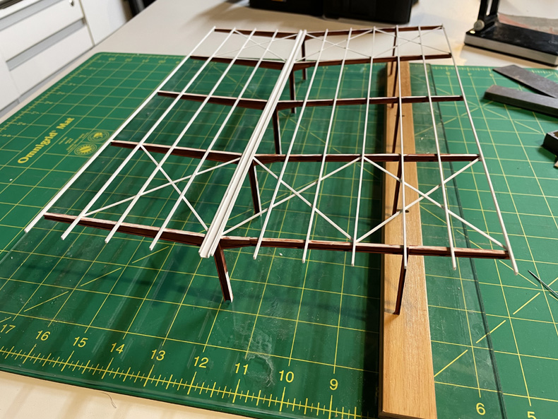
Framework construction
After checking measurements, the main posts will be Evergreen
4.8mm H beam, with 2.4mm H beam for the platform posts.
An Evergreen 4.8mm I beam (with a widening taper section at
the main post end) will join the two posts at under roof level.
The same size U channel in 4.8mm will be used for the channel
gutter, running the length of the shed and sitting on top of
the main vertical H beam posts.
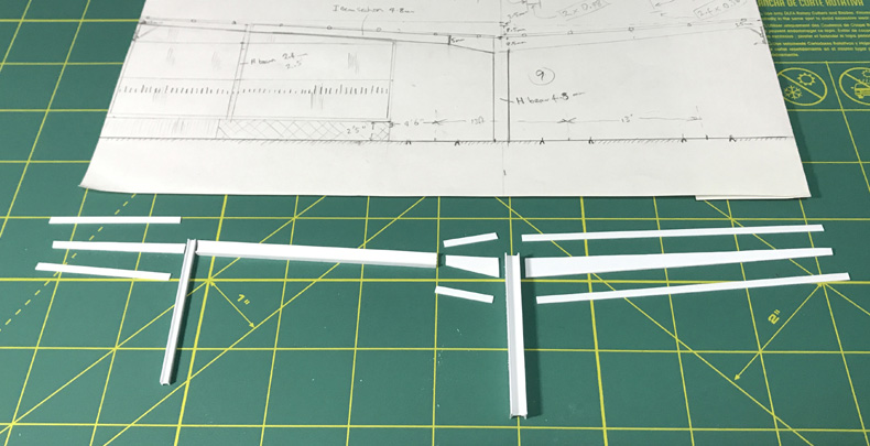
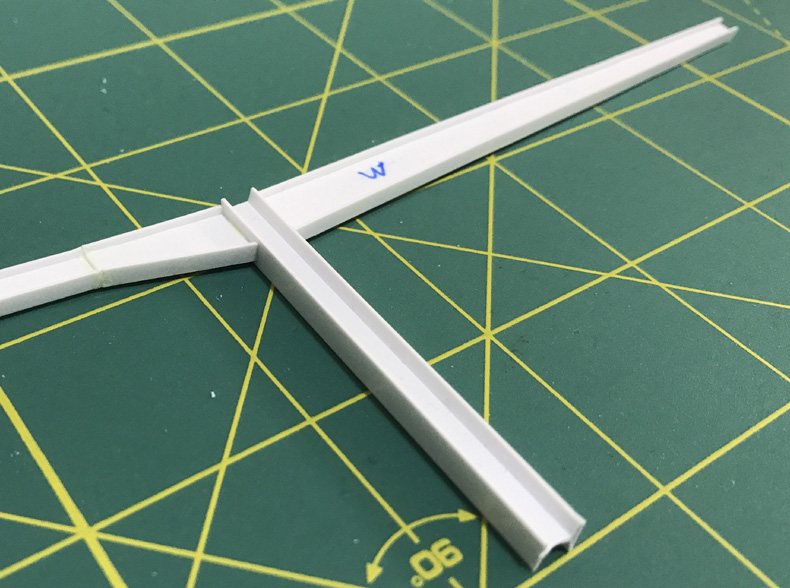
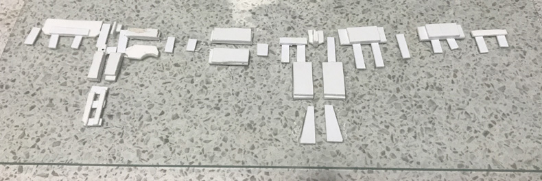
Parts ready to make up
the first rib.
The three tapered I sections
were made up from 0.5mm sheet and 0.5mm x 2.5mm strip.
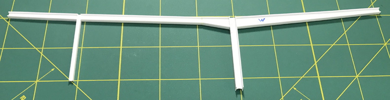
(Above and below)
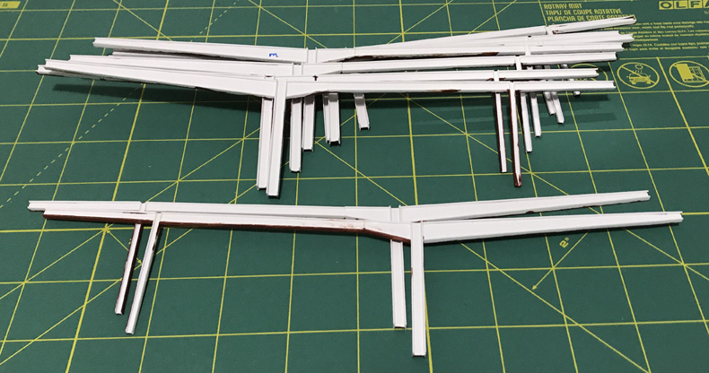
The first rib assembled.
Ok, now to make eight more of them. . . .
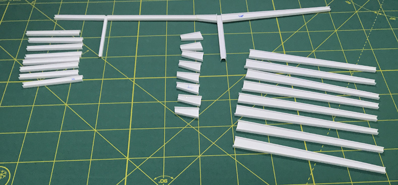
Taper sections built
for the other eight ribs - an evening's work in front of the
telly.
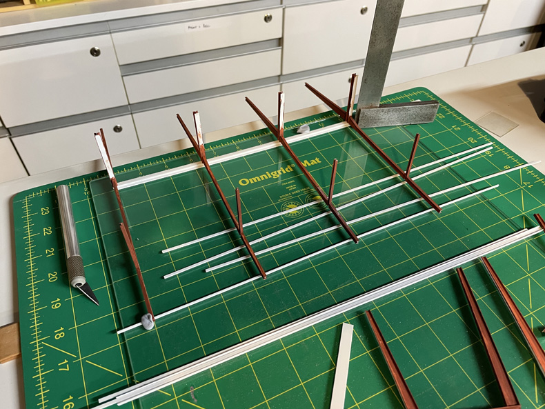
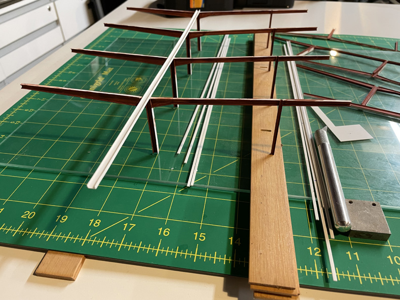
Using the one rib already made as a master, and laid flat
on a sheet of glass, various pieces of scrap plastic strategically
positioned around and under it to create a jig for the assembly
of further ribs. Once happy with positioning, all the bits -
except the rib of course - were superglued to the glass.
Ready to go!
Using a jig where you need to replicate accurately assembled
shapes like this, really really speeds up the process. I was
easily and accurately able to churn out the other eight ribs
required in a very short time. The time was in waiting for the
glue to set!
Nine ribs, undercoated
one side already.
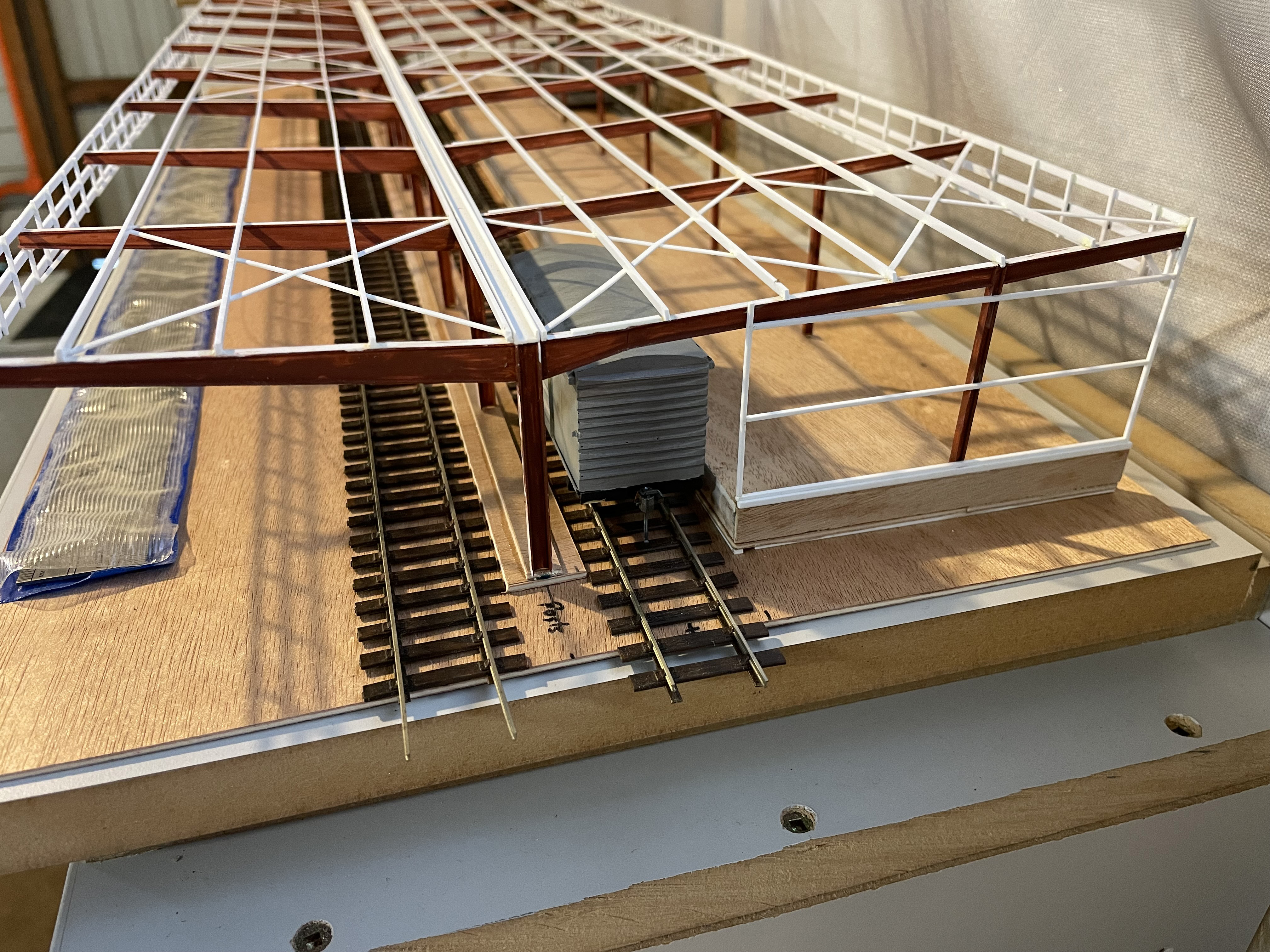
Finally, after three years, I can return, and proper assembly
begins!
Click on images for a closer, more scary look.
And as usual, sheet glass
is best for getting everything nice and flat in the same plane,
and the use of a cutting board and engineer's square give good
guides
for getting everything square in all dimensions.
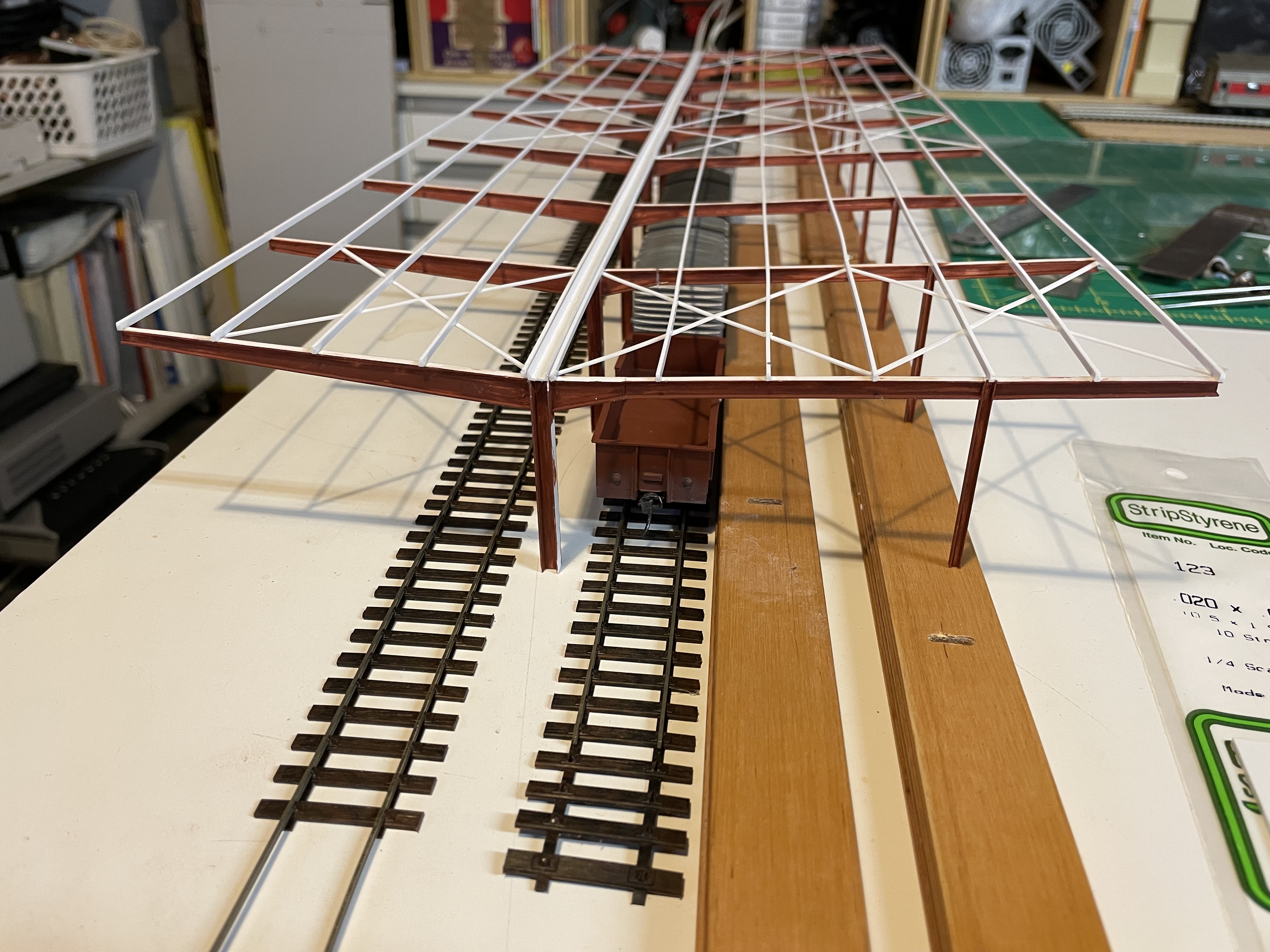
This is just half, now
standing upright to check all is well.
The "platform" is just 10mm worth of wooden venetian
blind slats to test with.
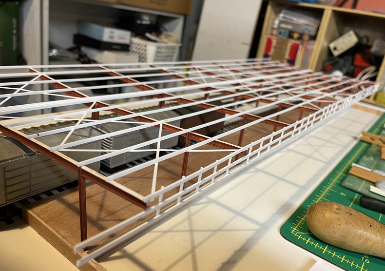
The thin styrene strips (2mm x 1mm) are going to be used as purlins.
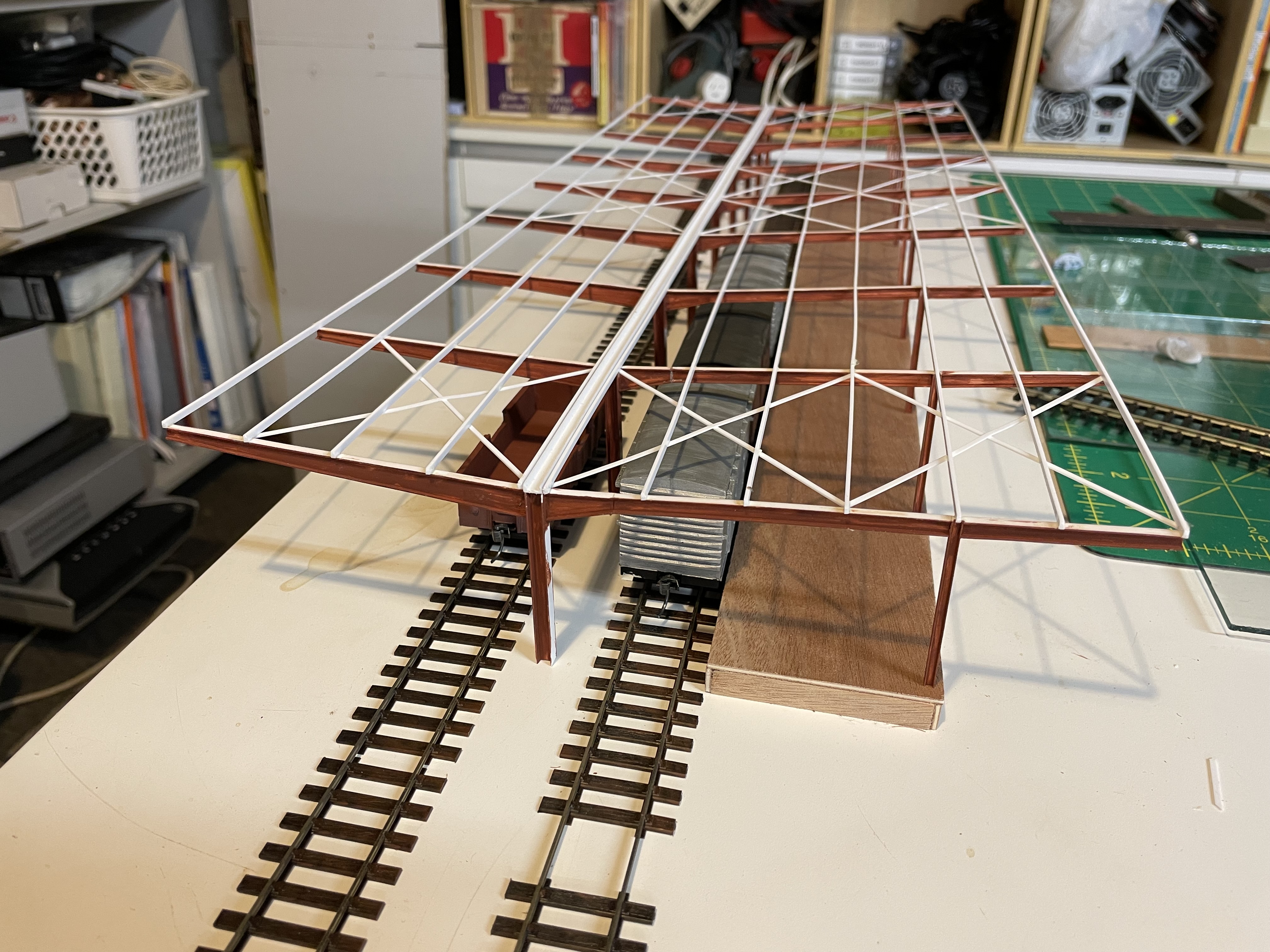
 Purlins in 2mm x 1mm,
and cross braces in 1.5mm x .5mm styrene strip added.
Purlins in 2mm x 1mm,
and cross braces in 1.5mm x .5mm styrene strip added.
Suddenly the structure doesn't feel so flimsy.

Second half has been
built and added to the first, and all mocked up with track, wagons
and "platform"
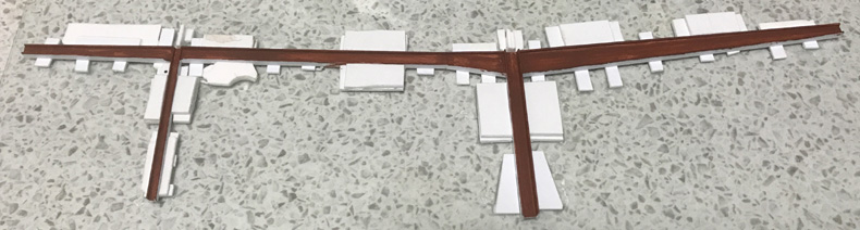
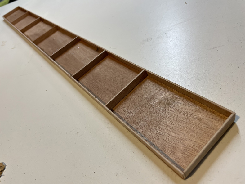 Platform construction
- simple top, sides, ends, and cross braces all from 2mm ply.
Platform construction
- simple top, sides, ends, and cross braces all from 2mm ply.
Glued together with PVA, then when set, beads of Araldite along
joins to strengthen.
And as usual with this sort of thing, all done on a large sheet
of glass to keep everything flat
Could have done the platform in plastic but had plenty of
this 2mm ply waiting to be used. And it was a nice change to
be working in wood, although the glue set wait times are frustratingly
much longer.
 Platform fitted in place.
It's a smidgen low as all plan heights were taken from rail height.
When it comes time to plant, it'll all be on shims depending
on trackwork chosen for these sidings.
 Added strips of 2mm ply
to platform ends, and another strip to the inside of road side
part so it becomes 4mm (1ft) thick.
Added strips of 2mm ply
to platform ends, and another strip to the inside of road side
part so it becomes 4mm (1ft) thick.
That wall and the platform end will be for the end framing to
sit on.
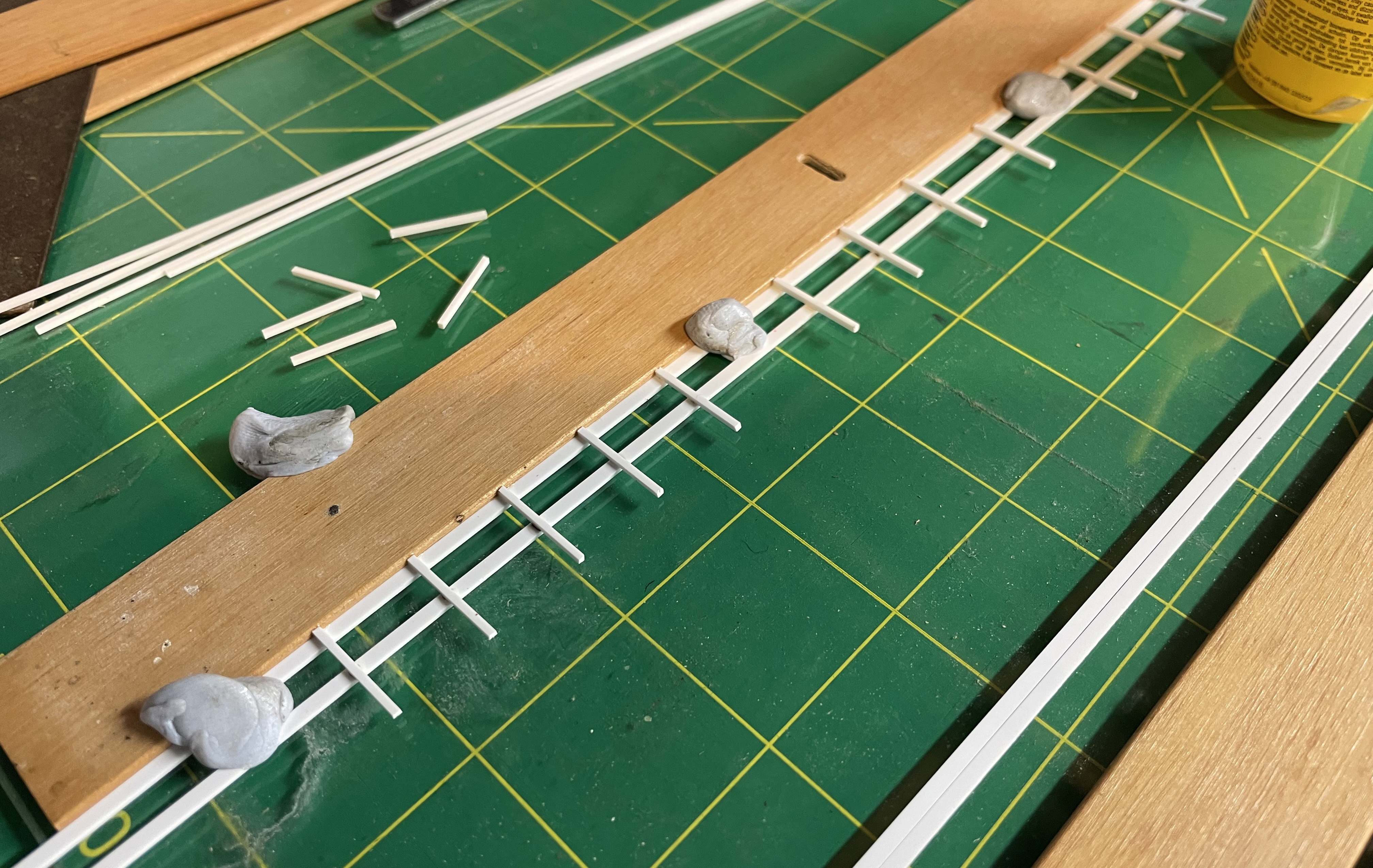
 Next is road (west) side
awning frame construction in 2 x 1 and 1 x 1 mm strips.. . .
Next is road (west) side
awning frame construction in 2 x 1 and 1 x 1 mm strips.. . .
 . . .and awning frame
fitted.
. . .and awning frame
fitted.
Needs a trim at the ends, and the other side still to construct.
 After more study, drcided
to go with 1mm square strip for the end frames.
After more study, drcided
to go with 1mm square strip for the end frames.
A sheet of glass and Lego bricks help get it all nice and square.
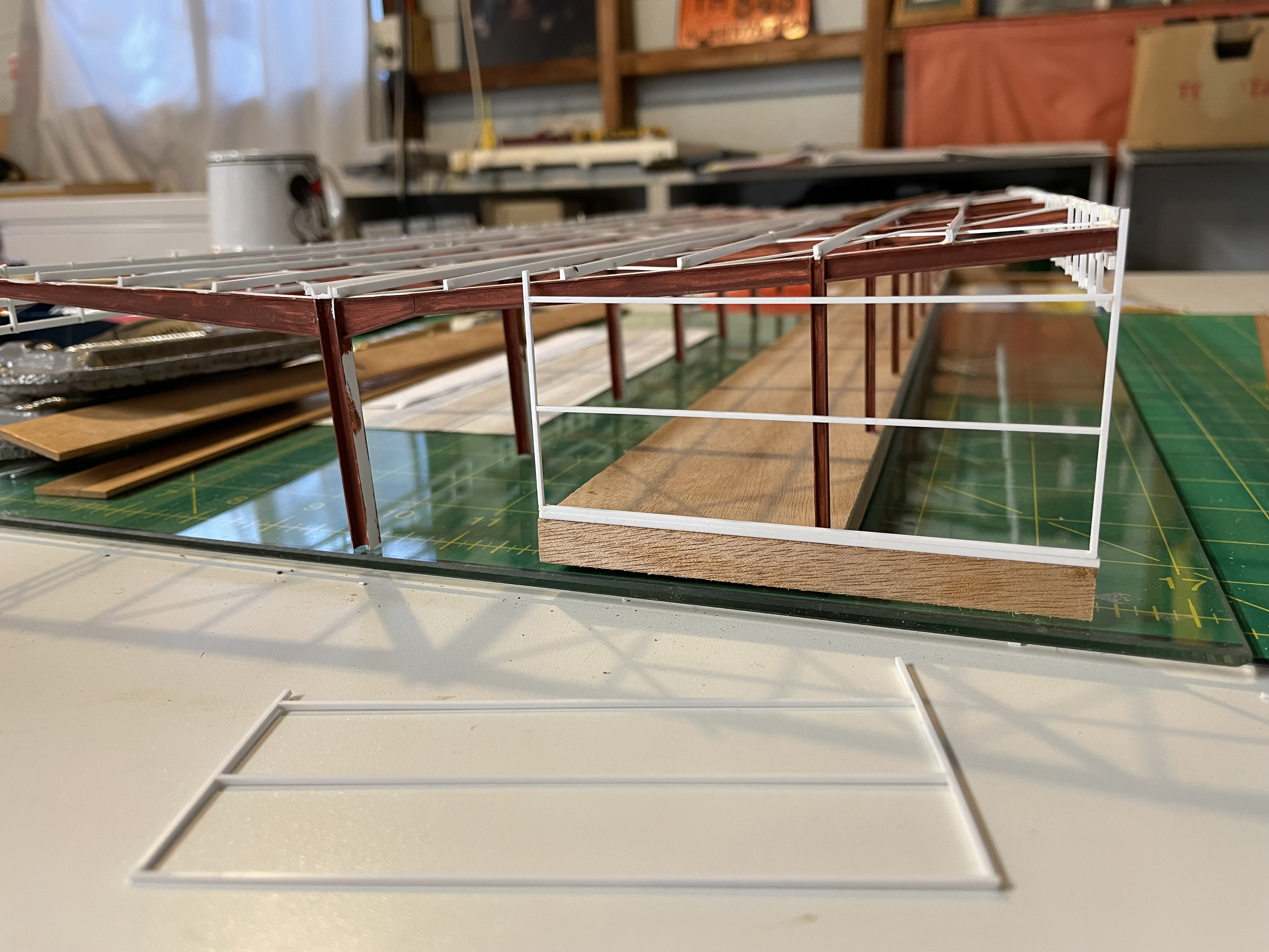
 One end frame fitted
for size.
One end frame fitted
for size.
Nearly ready to be fixed and clad.
 Ends now fitted, along
with 1mm square bracing for the awning.
Ends now fitted, along
with 1mm square bracing for the awning.
Now sizing up with a 2mm plywood base,
and getting everything up to track level using shims of ply and
styrene strip.
O scale corrugated material looks about the right size for
use on the roof, awnings, and end walls to represent the jumbo
size corrugated fibre cement material that was probably Hardies
SuperSix brand - 5.75" pitch instead of the domestic 3".
This stuff looks good for doing corrugated metal. . . from
Brunel
Hobbies in Oz.
They also have a tools for making it yourself in various scales.
But after a bit of Interweb research I decided to have a crack
at it myself, and created a separate page, Making
corrugated material.
More to come. . .
Home |